A listener recently asked for a tech tip explaining gear mod, so I figured instead of just doing one topic, I’d hit all-things gearing! Enjoy, guys!
So, what do gears do for us in our helis? A gear is a mechanical device that allows shaft power from one device – in our case, a motor or engine – to be transmitted to another shaft such as the main or tail shafts to drive a rotor. The best part about gears is that they not only transmit power, but they let you trade gear speed for gear torque or vice versa depending on the design of the gear train. This is where the concept of “gear ratio” comes in…
Everyone knows that we use a smaller, low-tooth count gear called a pinion on our power system to drive a larger, high-tooth count gear called the main gear, which in turn drives our main rotor head, right? But why do we do it this way? What we want is to convert the high speed and low torque of the power system shaft to the higher torque and lower speed needed to spin the large-diameter and heavy main rotor blades. So, the gear ratio tells you how you’re trading speed and torque…it’s a mechanical advantage or gain term, just like the bell crank ratios on your servos. It can be calculated as follows:
Gear ratio = Number of main gear teeth / Number of pinion teeth
This number is always greater than one on our helis and is usually expressed as “X:1.” Typical gear ratios for rc helis are from 6-9:1 depending on the power system and desired head speed. This also describes the ratio of speeds between the pinion and main gear (pinion speed:main gear speed) and the ratio of torques between the main gear and pinion (main gear torque:pinion torque). Let’s do a quick example…
We want to design a 700 class heli to fly with a head speed of 2,000RPM and we have three different power systems: an electric motor with a speed at maximum power of 20,000RPM, a nitro engine with a speed at maximum power of 16,000RPM, and a gas engine with a speed at maximum power of 12,000RPM. What gearing would you choose?
Well, since we have main shaft and power system shaft speeds and we know that the speed ratio is the same as the gear ratio, let’s calculate the gearing numbers and pinions we need if we want all three helis to run a 120-tooth main gear.
Electric
Gear ratio = 20,000RPM/2,000RPM = 10:1
Pinion tooth count = 120 teeth/10 = 12 teeth
Nitro
Gear ratio = 16,000RPM/2,000RPM = 8:1
Pinion tooth count = 120 teeth/8 = 15 teeth
Gas
Gear ratio = 12,000RPM/2,000RPM = 6:1
Pinion tooth count = 120 teeth/6 = 20 teeth
Alright, so now that you know how gearing works, let’s talk about a few more detailed concepts. First, gear mesh is the term used to describe how much “play” exists between two gears. If the gear teeth are pressed together so that there is no movement between them when you hold one gear and attempt to rotate the other, then you have a tight mesh. On the other hand, movement between the two gears is called loose mesh.
Usually, the ideal mesh is found by finding the high spot in the gear train’s rotation and setting it tight (no movement) at that location. The other portion of the gear’s circumference will then be just loose enough to not cause power-robbing friction from occurring. Remember, too tight mesh will cause friction that can cause power loss, vibrations, and gear overheating while too loose mesh will cause gear stripping.
Ok! On to gear module, or gear mod for short. Quite simply, gear mod is a number that describes the width of a tooth in millimeters. The gear mod of a gear train is determined by the designer and usually depends on two things: the amount of power being transmitted and the effect of gear ratio on mesh.
Thicker gear teeth have a higher mod number than thinner gear teeth. So, what’s the trade-off? Well, a higher gear mod can handle more power, but for the same ratio will have fewer engaged teeth at any given time. A lower gear mod will have good engagement for the same ratio, but will not handle as much power as the higher mod system. Now let’s calculate it:
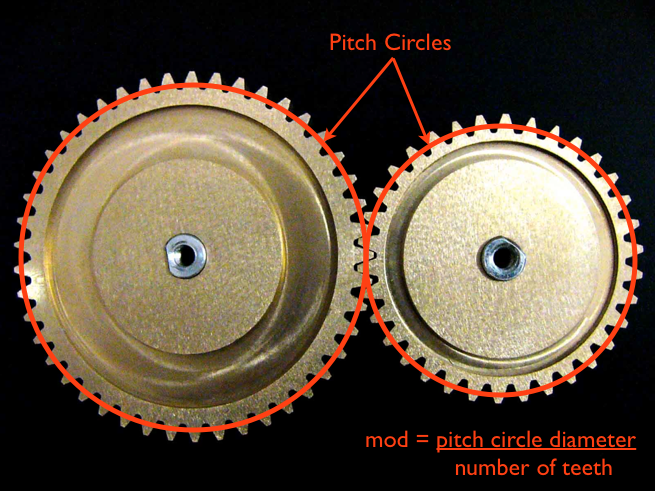
Gear mod = Pitch circle diameter / number of teeth
The pitch circle is the term used to describe the circle of one gear that JUST meets (tangent to) the other gear’s pitch circle. Check out the photo below and you’ll see what I mean…
What about that crazy thing called “electric gear ratio”? Well, some governors like the Skookum SK-540 internal governor ask you to input this number. So what is it and why is it different from the gear ratio we’ve been talking about? First, it’s not different…I’ll show you. 😉 Second, it’s simply your mechanical gear ratio times half the number of poles in your electric motor. See?
Electric gear ratio = (Number of main gear teeth / Number of pinion teeth)*(Number of motor poles / 2)
On to the final topic: gear type. Straight-cut (a), helical-cut (b), and herringbone (c) are the three types of gear that you’ll see in rc helis.
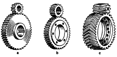
Straight-cut gears have teeth that are just that…straight! They’re cheap and easy to manufacture, but are the noisiest of the bunch and don’t handle high powers as well as the others. Helical gears cut the noise by using helix-shaped teeth that engage more gradually, but because of this, they also produce a thrust force along the axis of the shaft on which they spin, which necessitates the use of thrust bearings. Helical gears also have higher frictional losses than straight-cuts, so you should use lubricants to prevent loss of power and tooth wear. Finally, herringbone gears use two helical gear teeth sets placed next to each other in opposite directions. This eliminates the thrust force, but adds cost and complexity to manufacturing, so they tend to be rare in the rc heli world.
So, there you go…everything you ever wanted to know about gearing. If you’ve got any questions, comments, or suggestions for other topics, send me an email at .
– Justin