HeliBug PowerBug Alternator
Written by: Justin Pucci
As always, I must first thank those who made this review possible! In this particular case, we have Ali Azhar from HeliBug and Carey Shurley from Gas Powered Thoughts. Ali gets props for obvious reasons…he’s the owner of HeliBug, designer of the PowerBug, and the one who thought enough to give us here at RCHN the opportunity to review this cool new product. However, Carey Shurley also deserves a shout-out because of his constant nagging of Ali about doing a project like this…finally, Ali gave in and the PowerBug was born!
Product Description
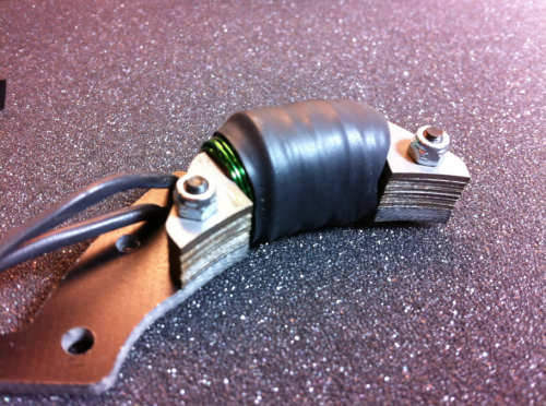
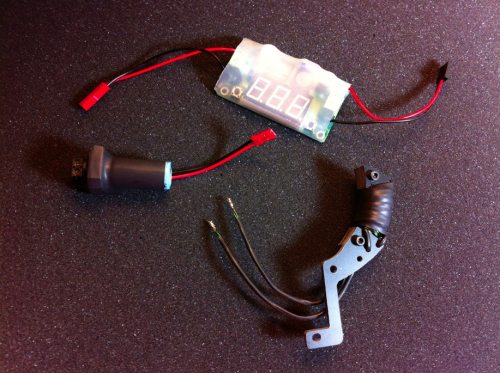
The HeliBug PowerBug Alternator is just that…an alternator for your gas-powered helicopter. It works exactly the same way the alternator in your car works to recharge your battery while the engine is running, but the design is vastly simplified so that it can fit on a heli. The unit itself is actually made up of three separate components: the alternator coil, the AC/DC converter, and the optional regulator. You can buy the alternator/converter combo for $129.99 from HeliBug and the regulator is provided for free as a limited-time offer (at least at the time of this review).
Let’s talk some technical, shall we? This device is what we refer to as a single-phase alternator, as it only uses one phase or coil pair to generate an AC current. It does this because it is placed near to the magnets on the fan of an RC-format gas engine. As the fan turns, the magnets and their associated magnetic field move quickly past the pick-up coil and induce a voltage across the coil wires that drives a current to the AC/DC converter. The converter first rectifies the AC signal with a set of diodes. This basically turns the wavy AC signal into a cleaner DC signal. Finally, the big bus capacitor further smooths the signal and acts as a reservoir for large transients in load current…this current then runs out to your regulator and into your electronics. Ok, enough of the theory, here are the specs:
Specifications
Maximum voltage at idle: 4.5-5.5V
Maximum voltage at full throttle (~12,000RPM): 10-16V
Maximum current at idle: 0.8-1.0A
Maximum current at full throttle (~12,000RPM): 2.2-3.2A
Installation
First off, remember that this only works on RC-format gas engines…no PUH or other variants. The good news about that is that you can use it on ALL RC-format applications, not just on your helis. So, if you’re like me and you’ve got a 1/5-scale Baja gas buggy, then you can pop one on that too!
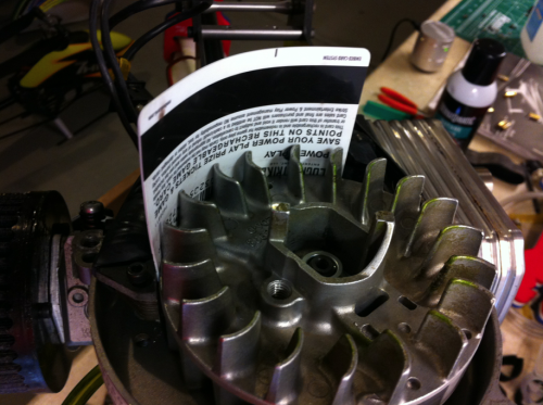
Honestly, I found the installation to be quite easy despite what I had heard from others. As I mentioned above, the alternator installs directly into your engine’s fan housing and actually uses the same two screws that secure your ignition coil system to the engine block. I installed this on my Whiplash Gasser and actually didn’t even need to take the engine out of the heli. Just remove the bottom plate that your heli uses to secure the engine into the airframe to gain access to the fan cover. Then, remove the fan cover. You’ll see your fan and a large, black plastic block with wires coming out of it…this is your ignition coil.
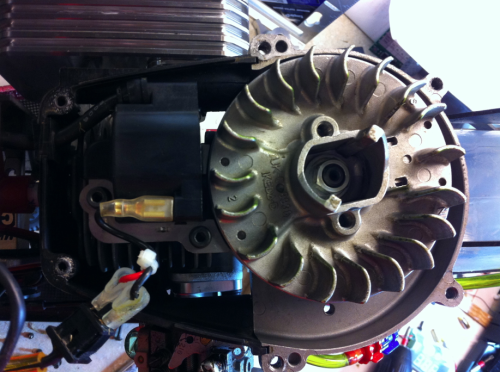
Note the two M4 bolts that flank one side of the ignition coil…those are what you’re going to remove. First, disconnect the wire that runs to your kill switch and then loosen the bolts. Before you go moving everything around, look out for the two plastic spacers that sit underneath the metal portion of the coil. The bolts slide through these and space the coil away from the engine block, so don’t lose them! Your engine should now look a bit like this…
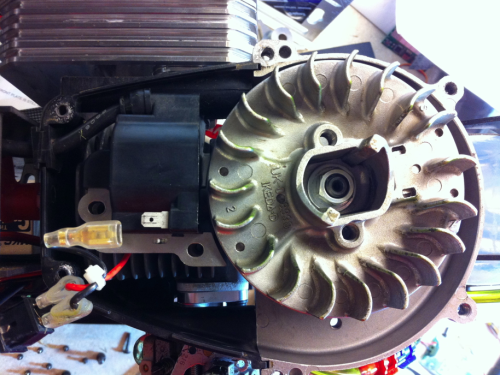
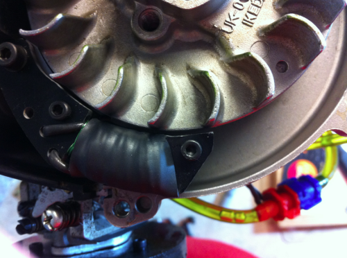
Next, install your alternator with the G10 plate lining up with the two bolt holes and the coil wrapping around the bottom side of the fan. You may need to play around with this step a bit, as it’s a tight fit. Depending on your alternator and fan housing, you may need to shave a bit off of one or the other so that when the magnets come around, they don’t pull the alternator into the fan and rub it. Once you’ve got it squared away, make sure that you get your coil spacing set correctly for your actual ignition coil…the spacing of the alternator isn’t critical, but the ignition coil spacing is. I use the good old-fashioned credit card trick where you simply bend the credit card around the fan between the fan outer diameter and the coils (about 1mm of spacing) and then tighten everything up from there. Done!
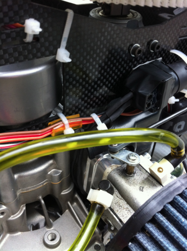
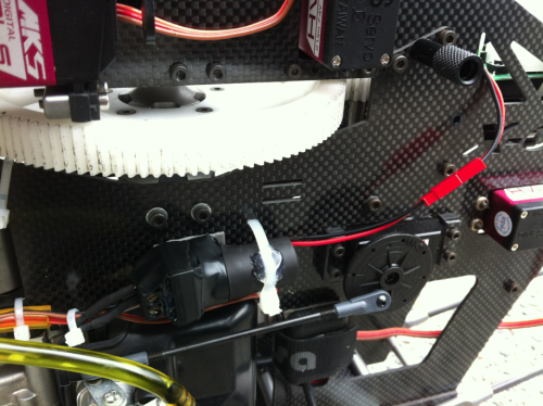
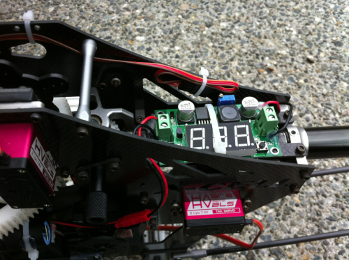
I then installed the AC/DC converter on the side of my heli with a zip tie and routed the wires from the alternator coming out through the fan shroud and plugging into the large green terminal block on the converter. Then I stuck the actual regulator up on top of the boom block with another zip tie.
Ok, now to get all the electronics set up correctly… The optional regulator allows you to set the DC output voltage that will be provided to your heli’s electronics. The whole idea here is to provide a constant voltage with the ability to source current to the electronics on demand. This system does NOT replace your receiver pack…it supplements it and, as such, t was designed to work with LiFe packs as well as NiMH and NiCd packs.
So, what we can do here is set our output voltage to that of one of the above-mentioned three battery chemistries and then when we’re running our heli and the pack voltage drops below that level, the alternator will kick in and top it back off again. This means that technically, you don’t ever need to charge your receiver pack again because the alternator will always keep it charged to the voltage that you set on the regulator. I would suggest against trying this with LiPo packs, as they’re far less robust to cell imbalance as compared to the LiFe’s and the nickel chemistries. Remember, this thing doesn’t have a balancer or anything fancy like that, it simply supplies current at a voltage determined and set by you!
Since I’m running a Gens Ace 2100mAh 2S LiFe pack on my Whiplash, I decided to set my regulator output voltage to 6.6V…why? Because 3.3V per cell is the steady-state LiFe pack voltage after the first few percent of capacity is bled off from 3.6V, so a 2S pack should spend most of its time around 6.6V. To do this, we can either power the regulator on the bench with a supply or battery or power up the heli WITHOUT BLADES ON AND WITH A SECOND PAIR OF HANDS and set the voltage while the engine is set at its governed headspeed or appropriate throttle curve. If you’re going to do the latter, PLEASE USE EAR PROTECTION AND DO THIS IN A WELL-VENTILATED AREA (i.e. outside)…hopefully, I don’t need to explain why.
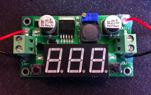
So, looking at the regulator face, you see a three-digit LED display and a black button on either side of it. The left button turns the display on and off and the right button switches the display between input and output voltages. First switch it to output voltage…you’ll know you’re on output voltage because a small LED will light up just above the right button. If the LED above the left button is lit, then you’re on input voltage. Next, find the blue box with the brass screw on top of it…this is your potentiometer and it will allow you to tune your output voltage.
Use a digital multimeter to check the voltage at the output by sticking the probes into the big green terminal block because the LED display isn’t always that accurate…mine was off by about 0.5V and that’s way too much error to get what we want out of this thing. As I said before, I set mine to 6.6V for my LiFe pack. Ok, now just make sure that the output of the regulator is plugged into your electronics via the receiver or flybarless system and you’re ready to go!
Flight Performance
This may actually be the shortest and most positive “flight performance” section that I’ll ever write in a review. Why?! It just works! Here’s the story…2100mAh LiFe pack, right? Whiplash Gasser…over two hours of ACTUAL stick time (about a gallon of fuel)…recharged the pack…I only put back 750mAh! That’s Less than 10mAh per minute consumption. What this means is that the 750mAh was likely the portion of pack capacity that existed above the 3.3V per cell (6.6V total) that I set the regulator to supply current at… Those stats speak for themselves!
Conclusion
So, after owning a gasser for over a year, I finally got a chance to give one of these cool alternator/generator things a try and let me tell you, I like it a lot! It gives me the ability to fly the gasser pretty much constantly without concern for recharging receiver packs every few flights and it also allows me to drop the size of my receiver packs down from the monster 2100mAh that I’m running now to something a lot more reasonable and lightweight. Also, unlike the generator systems out there, I can still use my spin-starter and ditch the pull-starter!
Like everything else though, there are a few downsides…1) it’s pretty heavy at ~120g, but at the end of the day we’re talking about a gasser, so you weren’t going to throw down electric-style anyway, right? 2) The other thing is that the regulator itself is quite bulky and difficult to find a good place to mount. The LED display doesn’t really add much value either, so a smaller board with just the tunable pot and smaller output terminals would be preferred…Other than that, this thing is a dream! Finally, at $129.99, some people may think it’s pricey, but I personally think that it’s a reasonable investment for what you ultimately get…convenience!
Again, I’d like to thank Ali Azhar at HeliBug and Carey Shurley at Gas Powered Thoughts for giving us here at the Nation the opportunity to review the HeliBug PowerBug Alternator and as always, thank you to the listeners for your continued support and interest in our product reviews.
– Justin