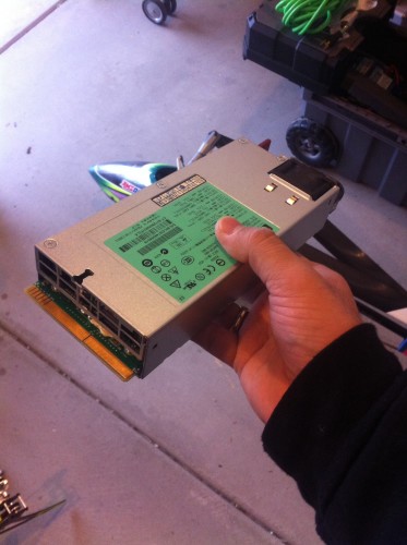
Alright, guys! I’ve gotten TONS of requests for a tech tip that describes how to deal with the mini-marvel that is the Hewlett Packard DPS-1200FB power supply, so here we go. For those of you who are curious about the specs, check this out: 1.5″ x 7.75″ x 3 1/2″ and weighing in at around two pounds each with a capability to supply 900W (75A at 12V). Now THAT’S crazy!
Before we get started, please read the disclaimer below.
DISCLAIMER: This is a description of a method that I have personally determined to be adequate for amateur modification of this particular server power supply and this supply ONLY. This is, in no way, meant to represent the best, safest, or even correct way to do things. Remember that we’re dealing with electricity here, which means you’re taking your life into your own hands. The responsibility is YOURS and no one else’s. Please proceed at your own risk and DO NOT attempt anything described herein without ensuring that you have taken all the necessary precautions to safeguard yourself and others from injury.
Ok, now that we’ve got that out of the way…
There are two parts to this tip. First, we’ve got to figure out how to get the damned power supply to even turn on and provide an output, right? This one is pretty simple… Familiarize yourself with your DPS-1200FB supply output board before you do anything. As you look at the printed circuit board at the back end of the supply, you should notice a few key features:
From left to right:
1. Six thin terminals labeled 33 through 38. The labels are actually only on 33 and 37, but you can fill in the blanks.
2. Two wide terminals labeled 51 and 64…these are your return (-) and +12V (+) output terminals, respectively.
Without connecting the correct thin terminals with the proper resistor, the supply will never provide output power (indicated by the green LED by the fan turning on). The reason for this is that when these supplies are plugged into a large server farm, these circuit boards connect into a set of matching terminals that allow the supply to operate correctly. Since we don’t have that, we’ve got to fool it into thinking the “safety” is off…
So, what you’re going to do is solder a resistor of 330-1000 Ohms between terminals 33 and 36 as seen in the photo below:
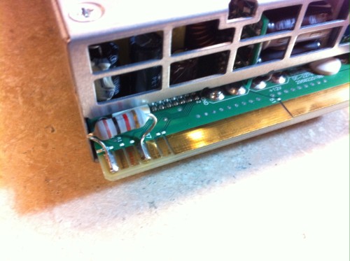
These resistors can be bought from Radio Shack for about $1 each and have leads that are easy to form to the dimensions of the supply terminals. The one shown in the photo is a 1W, 1000-Ohm metal film resistor.
To solder it correctly, tin the solder terminals first and then, holding the body of the resistor carefully with a pair of pliers, solder each leg down making sure that they are hardened before moving to the next one. Make sure that the leads do not come in contact with the case of the power supply or any other terminals or else your supply will not work correctly. Also, make sure that as you solder stuff on to your terminals, you don’t get any excess solder in the gap between adjacent terminals or you’ll short stuff out. I like to use a hobby knife to clean the areas in between the pads after I’m done soldering and I’d suggest that you get in the same habit so that you don’t run into any issues later on down the road.
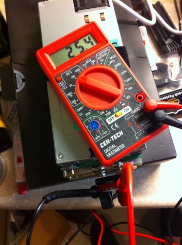
Before moving on, plug the supply into a wall socket and check first that the green LED comes on and then second, that you are measuring approximately 12V between the two wide terminals on the output circuit board using a digital multimeter. Depending on how your supply was used prior to you acquiring it, you may see a voltage between 11.7V and 12.7V. Don’t worry, I’ll show you how to adjust this later…
Ok, at this point, we’re almost ready to use our supply. Now all you have to do is decide what type of output terminals you’d like to use. I recommend either bullets soldered directly onto the two board terminal pads or female banana plugs. The banana plugs are generally more convenient, but you need to be careful to choose a set that can handle the kind of current that you’re going to be pushing. Let’s do the math really quick… 900W at 12V is an output current of 75A. Most banana plug systems can’t handle that, so please think this through.
If you do decide to go with a connector type of questionable capacity, then please make sure that you do a test charge first while monitoring the temperature of the output connectors with an IR temperature gun or something similar.
So, next up on the list of things to do is to figure out how to connect two of these in series so that we can get 24V on the output instead of just 12V. In order to do this, one of the two supplies need to be “floated” so that it’s output side is not grounded through the case. There are two methods for doing this:
1. Cut the input side 120VAC ground connection to the case or remove the grounding prong on the power cable. This maintains a connection between the chassis or case of the supply and the output, but will require the floating supply to be insulated externally so that it doesn’t short out to the other supply while operating. This is a pain and it’s not safe…
2. Maintain the input ground point and float the output board so that the case is still grounded and everything is safe!
You can probably guess that we’re going to do #2. I do NOT recommend doing #1, but there are a lot of people who do things that way, so please make sure you know what you’re doing and understand the implications of your actions before you go messing around with the input side grounding scheme.
So, on to #2…
1. First, make sure the supply is unplugged and powered down and then remove the top metal case from the supply you’d like to float.
2. Pull the rubber insulation cover from the top of the supply and set it off to the side. We’ll need this later, so do not damage it.
3. Carefully remove the fan housing and AC plug input socket. Make sure that you also pull the green LED out of its housing or you won’t be able to take the circuit card assembly (CCA) out of the case.
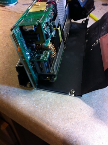
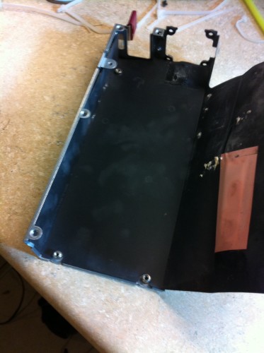
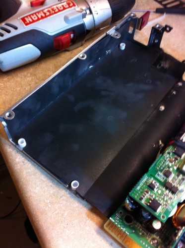
4. Unscrew the three Phillips head screws that hold the CCA to the bottom metal case and put them off to the side. At this point, you should be able to gently remove the entire CCA from the bottom half of the case and be left with the metal bottom and the black rubbery insulation cover.
5. Now, you’re going to need three nylon screws and nuts that will take the place of the three steel screws you just removed. This is how you’re going to float the board from case ground. I found a few really nice nylon screw/nut pairs at Home Depot and the work great, but you can use anything you’d like as long as it’s an insulating material like nylon.
6. Get out your drill and a drill bit of appropriate size to match the plastic fasteners that you’re using and VERY CAREFULLY drill out the three holes on the CCA so that they new hardware will fit. Do the same on the bottom of the case, but drill it from the outside so that the metal bosses pop out completely.
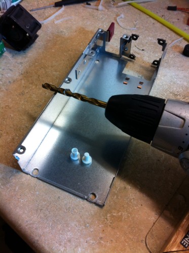
7. Now, make sure you can fit the plastic fasteners in and then replace the black rubber insulator cover and re-install the CCA, fan housing, and AC input socket. Make sure that the fasteners are secure and tight enough so that they will not come undone under normal handling and traveling conditions.
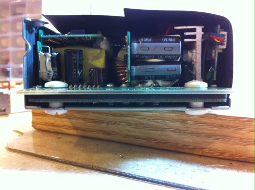
8. Before we go any further, reinstall the top case making sure that the black insulator goes back in place where it was originally. Once we’ve got the supply rebuilt, we need to ensure that our floating scheme worked. Using a digital multimeter in resistance measurement mode, check the resistance between the two output terminal pads an the metal outer case. You should read a very large number of “off-scale” if you did things correctly. This means that your output is no longer connected to the grounded case.
9. Next, power up the supply and verify using your digital multimeter that you’re getting approximately 12V across the output terminals. Congrats! You’ve successfully floated your power supply.
10. Now, to connect the floating supply in series with another supply, connect the positive terminal on the grounded 12V supply to the negative terminal on the floating 12V supply. Check again with your digital multimeter that you’re getting around 24V between the negative terminal on the grounded supply and the positive terminal on the floating supply before you plug your charger in.
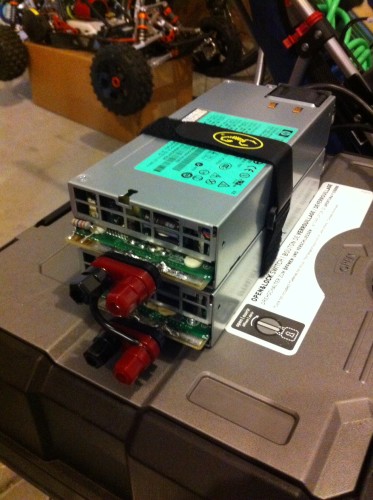
If you’ve gotten this far, then you should be ready to rock! Again, please make sure that you do a test charge where you closely monitor the progress of your new system. Take temperature measurements of the output terminals, wires, and cases to make sure that nothing is amiss. Once you’re confident that everything is running smoothly, you should be ready to blast those big packs with 1800W of 24V power!
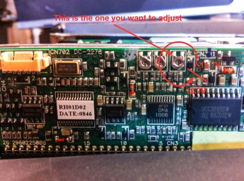
So, last but not least, you probably want to know how to adjust the output voltage on these things, huh? Easy. Power down your supply and remove the top case. Then pull the insulator off to the side again and look at the circuit board on the right side of the assembly when you’re looking at the supply from the output end. If you look close, you’ll see three small circular metal devices in a row with a flat edge on one side of each circle. These are trimming potentiometers and are used to tune various features of the circuit. The one you want is the third one (all the way to the right).
This is a one-turn, continuous pot where the flat represents the “dial” indicator. So, with the flat starting at around 4:30 on the clock, you get 11.7V and one full rotation later it’s at 12.7V…a little bit further and you’re back at 11.7V again. Get it? To turn this pot, very carefully use a pair of needle nose pliers and MAKE SURE THE SUPPLY IS UNPLUGGED! Check your output voltage with your digital multimeter each time you change the pot until you get what you’re looking for. Remember, if you have two supplies in series, you’ll have to do this twice. Since these supplies are effectively voltage sources, they stack well in series without voltage matching, so you don’t necessarily have to get their output voltages to match perfectly.
Once you’ve got everything set and working, make sure to close up the supplies and mark them so that you know which is the grounded and which is the floating. They’ll be safe to touch with your unprotected hands as well as together and you’ll still have the AC ground on the input sides. So, that’s about it! As always, if you’ve got any questions, you know where to reach me… Be safe and good luck!
– Justin